Electronic
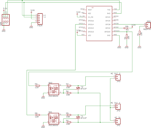
The watchdog IC U2 is not needed and should be removed from the PCB in the future. Same for snubber circuits C1 and R6 + C2 and R10.
If "AC IN" is connected to the 230 VAC on the power supply module, the two "OUT 1"/"OUT 2" can be used as software controlled 230 VAC outputs.
| Part | RS# | Description |
|---|---|---|
| JP1, JP2, JP3 | 821-8701 | 2 way PCB Terminal Block |
| KAM | 702-2937 | 6 way PCB Socket |
| OK1, OK2 | 691-2319 | MOC3063S-TA1 Optocoupler |
| R1, R2, R3 | 721-7820 | 0805 10kΩ Resistor |
| R4, R5, R6, R7 | 721-7707 | 0805 330Ω Resistor |
| R8, R9 | 721-6867 | 0805 120Ω Resistor |
| T1, T2 | 792-0709 | BT137S-600D TRIAC, 600V 8A |
| ESP | Ai-Thinker ESP8266 ESP-07 | |
| PCB | https://dirtypcbs.com/store/designer/details/8041/518/kamstrup-wifi-power | |
| PSU PCB | https://dirtypcbs.com/store/designer/details/8041/3578/psu-zip |


The 230 VAC power supply Kamstrup supply does not give enough current for wireless peak usage, so we built our own with a 2A switched mode power supply from AliExpress supplier Kuuco's store customized to 3.6 V to keep the Kamstrup meter happy.

The Eagle PCB can be found in the GitHub project