Skip to content
New issue

Have a question about this project? Sign up for a free GitHub account to open an issue and contact its maintainers and the community.

By clicking “Sign up for GitHub”, you agree to our terms of service and privacy statement. We’ll occasionally send you account related emails.

Already on GitHub? Sign in to your account

CE pin and rockchip 3588 boards #1017

Closed
ErikApption opened this issue Jan 25, 2025 · 23 comments · Fixed by #1018
Closed

CE pin and rockchip 3588 boards #1017

ErikApption opened this issue Jan 25, 2025 · 23 comments · Fixed by #1018
Labels

Comments

@ErikApption
Copy link

What radio module do you use?

nrf24l01 lpna

What driver board(s) do you use?

Orange pi 5 max

If using Linux, what OS are you using?

Linux 6.1.43-rockchip-rk3588 aarch64
No LSB modules are available.
Distributor ID: Ubuntu
Description:    Ubuntu 22.04.5 LTS
Release:        22.04
Codename:       jammy

If using Linux, what RF24 driver did you select?

SPIDEV (linux kernel)

Describe your problem

I am not able to receive anything on a RK3588 board. I suspect issue is the CE pin, because the numbering is unclear. The GPIO numbers (from gpio tool) always throw an invalid pin number but if I use the actual pin then I am not getting any reception. The radio is detected with spidev0.0 but I am not able to receive anything.

I haven't done too much digging yet in the rk3588 kernel to see what is behind the spidev logic... Has anyone been able to run a nrf24 with a rk3588 based board?

What is the RX code?

straight copy of multi receiver in python. Exact same code works on a RPi2

What is the TX code?

// no tx
@TMRh20
Copy link
Member

TMRh20 commented Jan 25, 2025

  1. In the multiceiver demo example there is a line radio.printDetails(); can you either un-comment or add this line and post the output here? Try using a pin that doesn't throw the invalid pin number error.
  2. Are you using the same type of PA+LNA module & setup with the RPi2 as well?

@ErikApption
Copy link
Author

This is my printDetails() - the output looks exactly the same on both the RPi2 and the Orange PI and it is exactly the same hardware (PA + LNA).

================ SPI Configuration ================
CSN Pin                 = /dev/spidev0.0
CE Pin                  = Custom GPIO22
SPI Frequency           = 10 Mhz
================ NRF Configuration ================
Channel                 = 5 (~ 2405 MHz)
Model                   = nRF24L01+
RF Data Rate            = 1 MBPS
RF Power Amplifier      = PA_LOW
RF Low Noise Amplifier  = Enabled
CRC Length              = 16 bits
Address Length          = 5 bytes
Static Payload Length   = 32 bytes
Auto Retry Delay        = 1500 microseconds
Auto Retry Attempts     = 15 maximum
Packets lost on
    current channel     = 0
Retry attempts made for
    last transmission   = 0
Multicast               = Disabled
Custom ACK Payload      = Disabled
Dynamic Payloads        = Enabled
Auto Acknowledgment     = Enabled
Primary Mode            = TX
TX address              = 0x65646f4e31
pipe 0 ( open ) bound   = 0x65646f4e32
pipe 1 ( open ) bound   = 0x65646f4e33
pipe 2 ( open ) bound   = 0x34
pipe 3 ( open ) bound   = 0x35
pipe 4 ( open ) bound   = 0x36
pipe 5 ( open ) bound   = 0x37

@2bndy5
Copy link
Member

2bndy5 commented Jan 25, 2025

If you have libgpiod installed, then you can use the included CLI tools. This might help identify the pin number and gpiochipX number on your system.

PS - I would also suggest using pyrf24 package instead of the individual wrapper in this repo.

@ErikApption
Copy link
Author

ErikApption commented Jan 25, 2025

wow I figured it out! so it looks like spidev talks by default to /dev/gpiochip4 - not sure why but CE works if you connect it to a GPIO 4 pin. GPIO4_A6 = 6 = RF24(6,0) - and I used the pyrf24 package. It is super handy.

@ErikApption
Copy link
Author

Found it, the gpiochip is hard coded and defined in https://github.com/nRF24/RF24/blob/master/utility/SPIDEV/gpio.h - would be nice to have a param to select the chip number for other boards

@2bndy5
Copy link
Member

2bndy5 commented Jan 25, 2025

it looks like spidev talks by default to /dev/gpiochip4

This was done to support RPi5. If the chip does not exist, then the lib will fallback to gpiochip0 (for backwards compatibility).

try {
gpioCache.openDevice();
}
catch (GPIOException& exc) {
if (gpioCache.chipInitialized) {
throw exc;
return;
}
gpioCache.chip = "/dev/gpiochip0";
gpioCache.openDevice();
}

If it the wrong chip for the system, then users can set the default at build time using RF24_LINUX_GPIO_CHIP defined.
#ifndef RF24_LINUX_GPIO_CHIP
/**
* The default GPIO chip to use. Defaults to `/dev/gpiochip4` (for RPi5).
* Falls back to `/dev/gpiochip0` if this value is somehow incorrect.
*/
#define RF24_LINUX_GPIO_CHIP "/dev/gpiochip4"
#endif

Building RF24

cd build
cmake .. -DRF24_LINUX_GPIO_CHIP="dev/gpiochip0"
make sudo make install

Building pyRF24

Requires cloning pyRF24 and init-ing the git submodules

export CMAKE_ARGS="-DRF24_LINUX_GPIO_CHIP=\"dev/gpiochip0\""
git clone --recurse-submodules https://github.com/nRF24/pyRF24.git
cd pyRF24
python -m pip install . -v

This also affects the attachInterrupt() exposed in RF24 (C++ only)

@2bndy5
Copy link
Member

2bndy5 commented Jan 25, 2025

would be nice to have a param to select the chip number for other boards

We won't be adding to the runtime overhead by adding a param to change this dynamically at runtime.

@ErikApption
Copy link
Author

This was done to support RPi5.

This makes sense and not a big ordeal to change the CS pin on the board. I think a note in doc about the pin number and mention that the lib will default to /dev/gpiochip4 on other non RPi boards could avoid this issue for other users. My understanding is that with spidev the pin corresponds to the gpio number on the current chip which is different from the gpiod number which aggregates all the chips with bank + group numbers.

@2bndy5
Copy link
Member

2bndy5 commented Jan 25, 2025

@ErikApption what is the the output for gpiodetect?

I suspect that the lib does not fall back to gpiochip0 because a gpiochip4 exists (but it isn't the chip that exposes the desired GPIO pins).

@TMRh20 Would it be possible to sym-link dev/gpiochip0 (targeting dev/gpiochip4) on RPi5? I cannot test this idea without an RPi5.

I think a note in doc about the pin number and mention that the lib will default to /dev/gpiochip4 on other non RPi boards could avoid this issue for other users.

The macro is documented, but the docs (build instructions and Linux usage doc) don't highlight this rare problem. TBH, this is the first time it has become a problem since we switched to Linux kernel's "character device" interface (for GPIO manipulation) almost a year ago.

It would be better if we had a RPi OS specific macro to detect when building on the RPi OS, moreso to detect the RPi5 (or newer).

@ErikApption
Copy link
Author

ErikApption commented Jan 26, 2025

@ErikApption what is the the output for gpiodetect?

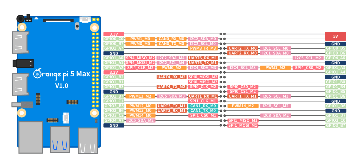
this is how it looks on rk3588, but only few of these lines end up being usable

weather@weather-opi:~$ gpiodetect
gpiochip0 [gpio0] (32 lines)
gpiochip1 [gpio1] (32 lines)
gpiochip2 [gpio2] (32 lines)
gpiochip3 [gpio3] (32 lines)
gpiochip4 [gpio4] (32 lines)
gpiochip5 [rk806-gpio] (3 lines)

It would be better if we had a RPi OS specific macro to detect when building on the RPi OS, moreso to detect the RPi5 (or newer).

the current aarm64 python package is excellent - a major upgrade from older version because you don't need to build the binaries separately anymore. This might be a rare issue but after doing some searches, there are other people struggling to run this with exotic boards. Could be also as simple as adding the gpiochip device in the prettyPrint() and some notes in the doc. I was almost ready to throw out my orange pi 5, until I figured out about the chips, lines and pins. Issue is that other packages like gpiod use a whole other pin numbering which makes it hard to diagnose.

@2bndy5
Copy link
Member

2bndy5 commented Jan 26, 2025

I also wrote a pure rust implementation (rf24-rs) with bindings to node.js and python. In the bindings' c'tors, there's optional parameters to select SPI bus and GPIO chip (separate from radio's CE and CSN pins). Unfortunately this hasn't been deployed yet.

@TMRh20
Copy link
Member

TMRh20 commented Jan 26, 2025

@2bndy5 I think something changed in RPi5...

Image

Image

gpiochip4 is now a sym-link?

Image

@2bndy5
Copy link
Member

2bndy5 commented Jan 26, 2025

That's what I suspected. On my RPi4 and RPi3, gpiochip4 resolves to gpiochip0.

$ ls /dev/gpiochip*
/dev/gpiochip0  /dev/gpiochip1  /dev/gpiochip4
$ file /dev/gpiochip4
/dev/gpiochip4: symbolic link to gpiochip0

Caution

We also need to verify this on a 32-bit RPi OS install. I'm currently using 64-bit on all my RPi machines.

I came across this when testing the node.js bindings of rf24-rs.

examples/node/ts/gettingStarted.ts

export class App {
  radio: RF24;
  payload: Buffer;

  /**
   * @param radioNumber The number (0 or 1) that identifies the which radio is used in
   * this example that requires 2 radios.
   */
  constructor(radioNumber: number) {
    // The radio's CE Pin uses a GPIO number.
    // On Linux, consider the device path `/dev/gpiochip<N>`:
    //   - `<N>` is the gpio chip's identifying number.
    //     Using RPi4 (or earlier), this number is `0` (the default).
    //     Using the RPi5, this number is actually `4`.
    // The radio's CE pin must connected to a pin exposed on the specified chip.
    const cePin = 22; // for GPIO22
    // try detecting RPi5 first; fall back to default
    const gpioChip = fs.existsSync("/dev/gpiochip4") ? 4 : 0;
    console.log(`using /dev/gpiochip${gpioChip}`); // ADDED FOR DEBUGGING (does not exist on remote)

    // The radio's CSN Pin corresponds the SPI bus's CS pin (aka CE pin).
    // On Linux, consider the device path `/dev/spidev<a>.<b>`:
    //   - `<a>` is the SPI bus number (defaults to `0`)
    //   - `<b>` is the CSN pin (must be unique for each device on the same SPI bus)
    const csnPin = 0; // aka CE0 for SPI bus 0 (/dev/spidev0.0)

    // create a radio object for the specified hardware config:
    this.radio = new RF24(cePin, csnPin, {
      devGpioChip: gpioChip,
    });

    // initialize the nRF24L01 on the spi bus
    this.radio.begin();

// ...

where

    const gpioChip = fs.existsSync("/dev/gpiochip4") ? 4 : 0;
    console.log(`using /dev/gpiochip${gpioChip}`);

always prints "using /dev/gpiochip4", even on my RPi3. BTW the examples work well (too well in case of scanner examples written for node.js)

examples/node/js/scanner.js output

Image
I added colors to better see which channels had the most noise...

@TMRh20
Copy link
Member

TMRh20 commented Jan 26, 2025

There are no gpiochip4 references in my 32-bit bookworm installs on RPi3 or RPi4 in /dev or using gpioinfo

So probably best to make gpiochip0 the default again?

@2bndy5
Copy link
Member

2bndy5 commented Jan 26, 2025

yep. Probably a good idea to add a note about RF24_LINUX_GPIO_CHIP in the install doc (or where ever the docs talk about adjusting the pin numbers).

@ErikApption It would be nice if you could provide a link to information that helped you find out about the rockchip pin numbers.

@2bndy5 2bndy5 reopened this Jan 26, 2025
@2bndy5 2bndy5 changed the title nrf24, CE pin and rockchip 3588 boards CE pin and rockchip 3588 boards Jan 26, 2025
@2bndy5 2bndy5 added bug and removed question labels Jan 26, 2025
2bndy5 added a commit that referenced this issue Jan 27, 2025
resolves #1017

This also adds some info to the docs that was requested in #1017
2bndy5 added a commit that referenced this issue Jan 27, 2025
resolves #1017

This also adds some info to the docs that was requested in #1017
@2bndy5
Copy link
Member

2bndy5 commented Jan 27, 2025

@ErikApption

I've added to the docs some info about GPIO chips on non-RPi systems. The docs preview for #1018 can be reviewed at our RTD project. I also cross-referenced the aforementioned Linux doc from the API docs about the CE pin parameter in RF24::RF24(ce_pin, ...) and RF24::begin(..., ce_pin, ...).

Let me know if further changes are desired.

@ErikApption
Copy link
Author

ErikApption commented Jan 27, 2025

@2bndy5 the edits in the PR are great. As for the pin numbering on the opi, the best is the official document that has the weird GPIO naming but I was not able to find any technical details on spidev, gpiochip and pin numbers.
Image

I guess one edit I would do is to say:

A device might have multiple GPIO chips, and the CE number in RF24 corresponds to the line for /dev/gpiochip0 (by default) which might be different from the official GPIO number and different from the actual PIN number.

@2bndy5
Copy link
Member

2bndy5 commented Jan 28, 2025

I was not able to find any technical details on spidev, gpiochip and pin numbers

These details are specific to the Linux kernel. I don't know of any doc'd details for the RPi also, namely how the kernel API is mapped out to actual hardware. We just kind of poke around until something works and then abuse what works 😆 . There's probably something about it in the system's DeviceTreeOverlay config 🤷‍, but that syntax looks more confusing than helpful.

@2bndy5
Copy link
Member

2bndy5 commented Jan 28, 2025

Just skimming the OPi5B manual (found here), I see the pin numbers are described as such:

The following uses pin No. 7 - the corresponding GPIO is GPIO1_C6 - the corresponding wPi serial number is 2

But this doesn't make any more sense as you found GPIO4_A6 = 6. The OPi (& BananaPi docs) still rely on installing a custom version of wiringPi (which has been officially dead for years). They then recommend using the hard-coded output of gpio readall (a CLI tool that installs with wiringPi).

@ErikApption
Copy link
Author

But this doesn't make any more sense as you found GPIO4_A6 = 6.

Indeed it is ridiculous and in addition to the wiringpi numbering they have the GPIO ones. The GPIO ones would be ultimately a good (and portable) convention because they combine bank + line into a single digit

@2bndy5
Copy link
Member

2bndy5 commented Jan 28, 2025

The GPIO ones would be ultimately a good (and portable) convention because they combine bank + line into a single digit

Arduino cores do this as well. I especially like how espressif aliased the ESP8266 pins with macros (like #define D2 ...) that correspond to the labels found on most of the MCU boards' silkscreen.

2bndy5 added a commit that referenced this issue Feb 1, 2025
resolves #1017

This also adds some info to the docs that was requested in #1017

* remove unnecessary members
* make cached chip FD static
@2bndy5
Copy link
Member

2bndy5 commented Feb 1, 2025

The doc changes are live and patch merged to master branch.

It will take another week to get this fix into pyRF24 though. I'll have to add something about RF24_LINUX_GPIO_CHIP usage in the pyRF24 README (near the enabling debug output example).

@2bndy5
Copy link
Member

2bndy5 commented Feb 7, 2025

Fix released in pyRF24 v0.4.5. Thanks again for bringing this to our attention.

Sign up for free to join this conversation on GitHub. Already have an account? Sign in to comment
Labels
Projects
None yet
Development

Successfully merging a pull request may close this issue.

3 participants