Likely any Arduino board with an AVR 328/328P or 32U4 which fulfils the following requirements should work with no or a just a little modification.
The controller chosen should:
- Have 5 V I/O or be 5 V tolerant, since the signals and power from the instrument are 5 V.
- Ideally have all 4 SPI pins available on connectors/pins (MOSI, MISO, SCK, /SS), otherwise some patching may be needed to get to them.
- Also have enough pins, and the correct voltage, for the display of choice.
- If you want to use the serial console for lots of debugging, you may want a microcontroller with built in USB for higher speed (as the 32U4). They also tend to be somewhat faster to program.
If you want to use USB for programming and debugging at the same time as the controller is connected to the instrument - check that the controller board does not connect the instrument 5 V with the USB 5 V. If it does, your computer or your instrument may become damaged, if you do not put diodes or other protection in the right places!
The 32U4 has 2.5 kB of RAM, the 328 has 2 kB.
If you want a fancy display with lots of graphics and still have a high refresh rate you may want something more powerful than an AVR 328/32U4. The SPI OLED with with 128*64 1 bit pixels could be driven at about 25-30 Hz frame rate when only the reading is updated, and with some trickery with the driver library - this is probable enough for most people.
If you want to use graphics or other fancy stuff it maybe be useful with more than 2.5 kB of memory, and probably a bit more program memory.
-
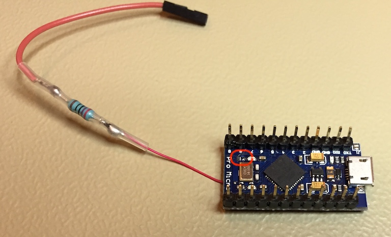
SparkFun Pro Micro 5V - 5 V 16 MHz - 32U4
- Works with some modification to reach the /SS pin - see below.
- Desoldering of the resistor to the RX LED, R4, needed - see below.
- Does NOT have protection of 5 V feeds - take care when connecting so that you don't damage things!
-
Arduino Nano - 5 V 16 MHz - ATmega328
- All 4 SPI pins available on headers!
- Need to remove the L LED or its resistor (sits on the SCK line) - see below.
- Does NOT have protection of Vin feed - take care when connecting so that you don't damage things!
-
Arduino Micro
- All 4 SPI pins available on headers!
- Desoldering of the resistor to the RX LED recommended.
- 5 V protection unknown
-
Adafruit Atmega32U4 Breakout board - 32U4
- All 4 SPI pins available on headers!
- Does NOT have protection of 5 V feeds - take care when connecting so that you don't damage things!
-
Arduino Leonardo - 32U4
- SPI pins SCK, MOSI, MISO on programming header.
- /SS probably reachable on the RX LED, maybe somewhere else, may need some soldering.
- Does NOT have protection of 5 V feeds - take care when connecting so that you don't damage things!
- PJRC Teensy 2.0, Atmega32U4 5 V
- All 4 SPI pins available on headers!
- Arduino pin assigment different from Pro Micro - needs some work.
- 5 V protection unknown
-
Adafruit Pro Trinket - 5V 16MHz - ATmega328P
- Uses some kind of USB bitbanging for programming, potentially flaky.
-
Adafruit ItsyBitsy 32U4 - 5V 16MHz:
- No /SS trace - need to solder to chip
- Diode from USB 5 V to internal, but not from a directly connected 5 V source.
- No /SS trace - need to solder to chip
-
Adafruit Feather 32U4 Basic Proto
- 3.3 V - will need level translators
On the Arduino Pro Micro, the /SS signal does not have a board pin, it is only connected to the resistor for the RX LED. To connect to it. you will have to solder directly to the board or to the chip.
The strips and solder pads are easily torn from the board, be careful. Preferably, you connect to it on a via (a hole that connects the wire through the board) to get better mechanical stability, and it may be easier to do it on the non-component side. Gently remove the solder mask (the insulation that covers the copper strips) by scratching with something sharp, and solder directly to the copper over the via. Be careful to only remove the solder mask on the wire you want to solder, or you may easily get a short to other wires.
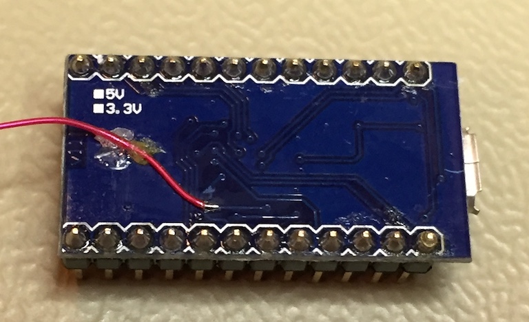
/SS wire soldered to a via, and glued down for stability. You could also solder the resistor directly between the via and the SS_OUT pin.
The resistor to the LED on the /SS line is removed to not have to drive that too with the SS_OUT pin.
The Arduino Nano has a "L" LED on the SPI SCK line. This must be removed, since otherwise the instrument's VFDSCLK would have to drive that too, and that will not work if the the protection resistor is in place on the VFDSCLK line.
On this particular Arduino Nano, the resistor is a separate component and could be removed. On others versions, the resistor may be in a package of 4 resistors, and it is probably easier/better to remove the "L" LED itself.
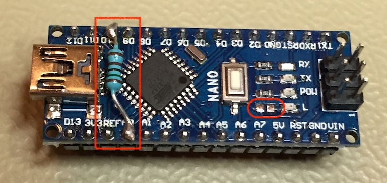
- Left - resistor from SS_OUT to /SS soldered directly to the board, for convenience.
- Right - resistor to "L" LED removed to not load the SPI SCK line from the instrument (which would not work with the protection resistors on the wires from the instrument).